Anemometer Calibration Standards
Anemometers are calibrated in accordance to Annex F of IEC 61400-12-1 “Wind turbines – Part 12-1: Power performance measurements of electricity producing wind turbines”. Although the calibration procedure refers to cup anemometers, it is widely accepted for the calibration of any type of anemometer.
The equipment used for the calibration is:
- A wind tunnel: Wind tunnels are large tubes with air moving inside. They have a fan which moves the air inside. The fan must have straightening vanes to smooth the airflow. The instrument under test is placed in the middle of the tunnel and it is fastened so it does not move.
- Pitot tubes: They are pressure measuring instruments used to measure fluid flow velocity. The pilot tube is a slim tube which has two holes on it. The front hole is placed directly into the fluid flow and it measures the stagnation pressure. The side hole measures the static pressure. By measuring the difference between these pressures, the dynamic pressure can be obtained according to Bernoulli’s formula, which can be used to calculate airspeed.
There are several requirements for anemometers’ calibration that must be taken into account:
- All transducers and measuring equipment shall have traceable calibrations. Calibration certificates and reports shall contain all relevant traceability information.
- The pitot tubes used must be calibrated for appropriate wind speed ranges and be documented.
- Prior to every calibration, the setup must be verified by means of comparative calibration of a reference anemometer.
- The repeatability of the calibration shall be verified.
- An assessment of measurement uncertainty shall be carried out in accordance with ISO guidelines.
There are also special requirements for the wind tunnel. The presence of the anemometer shall not substantially affect the flow field in the wind tunnel. The flow across the area covered by the anemometer shall be uniform. Flow uniformity can be estimated using velocity sensing devices, i.e. pitot tubes, hot wires or Laser Doppler Velocimetry. The flow shall be uniform to 0.2 %. The wind tunnel calibration factor, which gives the relation between the conditions at the reference measurement position and those at the anemometer position, shall be appraised using pitot tubes. In order to assure the repeatability of the facility, five calibrations of a reference anemometer shall be performed. The maximum difference between these calibrations should be less that 0.5% at 10 m/s wind speed.
During calibration the anemometer shall be mounted on top of a tube in order to minimise flow distortion. This tube shall be of the same dimensions as the one on which the anemometer will be mounted in service in the free atmosphere. Mounting arrangements can have dramatic effects on instrument sensitivity, particularly if the ratio of tube diameter to rotor diameter is high.
It is important to ensure that the anemometer is not influenced by the presence of any reference wind speed measurement equipment.
The pitot tubes shall be positioned at the test section perpendicularly to the flow field of the wind tunnel as accurate as possible. The maximum declination allowed is 1o. The anemometer shall be positioned at the test section perpendicularly to the flow field of the wind tunnel as accurate as possible. The maximum deviation allowed is 1 o.
Calibration Procedure
Before the calibration procedure begins, the anemometer shall run for about 5 minutes in order to avoid the fact that large temperature variations may influence the mechanical friction of the anemometer bearings.
Calibration shall be performed under both rising and falling wind speed in the range of 4 m/s to 16 m/s with steps of 1 m/s or less. By measuring both increasing and decreasing steps, it is possible to identify whether hysteresis effects are present in the measuring equipment.
The sampling frequency shall be at least 1 Hz and the sampling interval at least 30 s. Before taking readings at each wind speed, adequate time has to be allowed in order to establish stable flow conditions. This typically takes 1 minute, but it varies from facility to facility.
The air density (ρ) shall be calculated according to the following formula:
![]()
Where:
B is the barometric pressure (Pa)
T is the absolute temperature (K)
φ is the relative humidity (range 0 to 1)
Ro is the gas constant of dry air (287.05 J/kgK)
Rw is the gas constant of water vapour (461.5 J/kgK)
pw is the vapour pressure (Pa)
![]()
Where vapour pressure pw depends on the mean air temperature.
The mean flow speed ( ) at anemometer position is calculated from mean differential pressure Δpref at reference position according to the following equation:
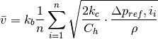
Where:
Ch is the pitot tube head coefficient
kc is the wind tunnel calibration factor
kb is the blockage correction factor
n is the number of samples within the sampling interval
After the calibration, an uncertainty analysis shall be performed. The uncertainty of measurement comprises of both type A and type B uncertainties, as described in EA-04/02 “Expression of the Uncertainty of Measurement in Calibration”. The following parameters shall be taken into account:
- Flow speed measurement uncertainty (pitot tubes, transducers, air density evaluation, etc.)
- Frequency measurements
- Wind tunnel calibration
- Flow variability in the vicinity if the anemometer.
Written by Sofia