Calibration of gas meters has become a necessity nowadays. Several methods are applied for performing gas meters’ calibration. The most common ones are:
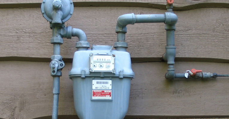
- Bell Prover: This is actually a calibrated vessel with well-known volume characteristics. It is often used as a primary standard. The Bell Prover provides a certain volume to the gas meter under test and thus a direct comparison between the meter’s reading and the volume’s value can be performed. This method is mainly used for calibrating small domestic / diaphragm meters.
- Gravimetric method: A very accurate weighing scale is used to define the amount of gas that actually flows through the meter during the calibration procedure. This method is considered to be very accurate.
- Test Bench: It is a complete system which uses master meters as reference standards. The same amount of volume flows through the master meter and the gas meter under test, and the two meter readings are compared to each other. This method is widely used by many calibration laboratories all over the world. Depending on the size of the master meters, high flowrates can be achieved and very large gas meters can be calibrated.
Before proceeding with the analysis of the Test Bench method of calibration, it is important to give some information about the metrological characteristics of the most common types of gas meters.
When a gas meter is calibrated, the result reported in the calibration report is the % Error of Indication which must be measured in specific flow points (depending on the meter’s type and rangeability). Error of Indication (f) is defined as follows:
[math]f=\frac{V_{MUT}-V_{TRUE}}{V_{TRUE}}-100 \%[/math]
Where:
VMUT = Volume Reading of the MUT
VTRUE = Actual Volume that flowed through the MUT
Based on these measurements, a calibration curve can be included in the calibration report. A typical calibration curve can be seen below:

The black curve indicates the Error of Indication of the gas meter in several flow points, while the red lines represent the error limits (maximum permissible error) for the specific type of meter. Error limits as well as measurement flow points are specifically defined within the corresponding European Standards for each type of gas meter.
Diaphragm Meters
According to EN 1359 the error limits of Diaphragm gas meters are shown in the following table:
| Diaphragm Gas meter Error Limits | |
| Flow Rate Q | Limits |
| Qmin ≤ Q < 0,1Qmax | ± 3,0 % |
| 0,1Qmax ≤ Q ≤ Qmax | ± 1,5 % |
The flow points for the calibration of a diaphragm meter are Qmax, 0,2Qmax, Qmin.
Rotary Displacement meters
For Rotary Displacement meters, the error limits are defined according to EN 12480:
| Rotary Displ. Gas meter Error Limits | |
| Flow Rate Q | Limits |
| Qmin ≤ Q < Qt | ± 2,0 % |
| Qt ≤ Q ≤ Qmax | ± 1,0 % |
Where Qt (Transitional Flowrate) is given by the following table:
| Flowrate Range (Qmin/Qmax) | Qt |
| ≤ 1:20 | 0,20 · Qmax |
| 1:30 | 0,15 · Qmax |
| 1:50 | 0,10 · Qmax |
| > 1:50 | 0,05 · Qmax |
EN 12480 also specifies that the meter must be calibrated at the following flow points depending on the meter’s rangeability (Qmin/Qmax):
| Test flow rates in % of Qmax | |
| Rangeability | |
| 1:10 to 1:30 | ≥ 1:50 |
| Qmin | Qmin |
| 5 | 5 |
| 10 | |
| 15 | |
| 25 | 25 |
| 40 | 40 |
| 70 | 70 |
| 100 | 100 |
Turbine meters
Turbine gas meters are calibrated according to EN 12261 which specifies the following error limits:
| Turbine Gas meter Error Limits | |
| Flow Rate Q | Limits |
| Qmin ≤ Q < Qt | ± 2,0 % |
| Qt ≤ Q ≤ Qmax | ± 1,0 % |
Where Qt (Transitional Flowrate) is given by the following table:
| Flowrate Range (Qmin/Qmax) | Qt |
| 1:10 | 0,20 · Qmax |
| 1:20 | 0,20 · Qmax |
| 1:30 | 0,15 · Qmax |
| ≥ 1:50 | 0,10 · Qmax |
The test flow rates for turbine gas meters are defined as follows:
|
Test flow rates in % of Qmax |
|||
|
Rangeability |
|||
|
1:10 |
1:20 |
1:30 |
1:50 |
|
2 |
|||
|
3 |
|||
|
5 |
5 |
5 |
|
|
10 |
10 |
10 |
|
|
15 |
|||
|
25 |
25 |
25 |
25 |
|
40 |
40 |
40 |
40 |
|
70 |
70 |
70 |
70 |
|
100 |
100 |
100 |
100 |
Calibrating gas meters with the Test Bench method

The Test Bench consists of:
- Two master meters of high accuracy
- Control valves for flow adjustment
- A fan working in suction mode
- Temperature transmitters
- Pressure Transmitters
- Software for communication and data processing
In the above figure the master meters used are one G16 and one G650 covering a total flow range of 0,5m3/h to 1000 m3/h. Usually rotary displacement meters with dual impellers are used in order to eliminate pulsation and resonance to the flow profile. In large test benches, where high flow rates must be achieved, turbine meters are also used as master meters.
In the case that the Calibration Medium is air at atmospheric pressure (which is an acceptable method for calibrating gas meters which operate at a pressure lower than 4 bar, as defined in EN 12261), the principal of operation of the Test Bench is described below.
The air enters through the filters (with the fan operating in suction mode) and flows through the master meter. The flow is adjusted via the control valves and the speed of the fan. The air passes through the meter under test and returns to the room exiting from the fan.
A temperature and a pressure sensor are placed on each meter (master meter and meter under test).
The test bench must have the capability to monitor the pressure drop at the meter under test as well as leakages at any part of the installation.
During the measurement (at each flow point) the following data are measured at the master meter and at the meter under test:
- The pulses
- The temperature
- The pressure
- The measurement time
- The barometric pressure
The indication error of the meter under test results from the comparison of the readings of the meter under test and the master meter and is given from the following formula:
[math]f_{MUT}=(\frac{V_{MUT}-(1+f_{STD}/100)P_{MUT}-T_{STD}}{V_{STD}-P_{STD}-T_{MUT}}-1)-100 \%[/math]
Where:
[math]V_{MUT}=\frac {N_{MUT}}{F_{MUT}}[/math]and
[math]V_{MUT}=\frac {N_{MUT}}{F_{MUT}}-\frac{t_{MUT}}{t_{STD}}[/math]Where:
VMUT : The volume of the meter under test
VSTD : The volume of the master meter
fSTD : The error of indication of the master meter (taken from the master meter’s calibration report)
PMUT : The pressure measured at the meter under test
PSTD : The pressure measured at the master meter
TMUT : The temperature measured at the meter under test
TSTD : The temperature measured at the master meter
NMUT : The number of pulses of the meter under test during the measurement
NSTD : The number of pulses of the master meter during the measurement
FMUT : The pulse value of the meter under test (written on the meter’s index)
FSTD : The pulse value of the master meter (taken from the calibration report)
tMUT : The measurement time of the meter under test
tSTD : The measurement time of the master meter
Specifications regarding the pressure and temperature measurement points, the upstream and downstream piping and the pressure loss measurement are mentioned in the relevant European Standards (EN 12480, EN 12261, etc.).
Useful information regarding construction and operation of Test Benches are also given in PTB Band 29 Guide “Testing of volume gas meters with air at atmospheric pressure”.
Measurement Uncertainty
When using a Test Bench to calibrate gas meters, similar to the one described above, there are several sources of measurement uncertainties:
- Repeatability of the meter under test
- Uncertainties resulting from the calibration of the temperature sensors, pressure sensors, barometer and master meters
- Fluctuation of pressure and temperature during measurement
- Drift of the sensors and the master meters
- Clock pulses are truncated due to the “A gated by B” method
- Limited resolution of the sensors, the master meters and the meter under test
Based on the formula mentioned above:
[math]f_{MUT}=(\frac{V_{MUT}-(1+f_{STD}/100)P_{MUT}-T_{STD}}{V_{STD}-P_{STD}-T_{MUT}}-1)-100\%[/math]
The standard uncertainty of measurement can be calculated by the following method:
[math]u(f_{MUT}=\sqrt{\sum(\frac{\partial f_{MUT}}{\partial xi})^2-(u(xi))^2}[/math]
Where:
xi is each measurement component (pressure, temperature, etc)
u(xi) is the standard uncertainty of each xi
[math]\frac{\partial f_{MUT}}{\partial xi}[/math]is the partial derivative of fMUT related to each xiA typical uncertainty value resulting from a measurement similar to the one described above, can be around 0,3%.
The same measurement philosophy can be used for high pressure measurements with natural gas as test medium. In this case the calculations are more complicated, since many more quantities affect the measurement (pressure, natural gas composition, etc).
In both cases, high or low pressure, air or natural gas, the calibration method must be well documented and validated, since gas meters are mainly used for billing processes. One way to achieve this is accreditation according to ISO 17025.
Written by Sofia


Comments are closed.